
Refer to the characteristic curve of a typical rectifier(diode) in the figure below. The forward characteristic of the curve we have previously described above in the DIODE section. It is the reverse characteristics we will discuss here.
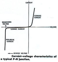
Notice that as the reverse voltage is increased the leakage current remains essentially constant until the breakdown voltage is reached where the current increases dramatically. This breakdown voltage is the zener voltage for zener diodes. While for the conventional rectifier or diode it is imperative to operate below this voltage; the zener diode is intended to operate at that voltage, and so finds its greatest application as a voltage regulator.
The basic parameters of a zener diode are:
(a) Obviously, the zener voltage must be specified. The most common range of zener voltage is 3.3 volts to 75 volts, however voltages out of this range are available.
(b) A tolerance of the specified voltage must be stated. While the most popular tolerances are 5% and 10%, more precision tolerances as low as 0.05 % are available. A test current (Iz) must be specified with the voltage and tolerance.
(c) The power handling capability must be specified for the zener diode. Popular power ranges are: 1/4, 1/2, 1 , 5, 10, and 50 Watts.
Leave A Comment