
The varactor diode symbol is shown below with a diagram representation:
![]()
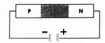
When a reverse voltage is applied to a PN junction, the holes in the p-region are attracted to the anode terminal and electrons in the n-region are attracted to the cathode terminal creating a region where there is little current. This region, the depletion region, is essentially devoid of carriers and behaves as the dielectric of a capacitor.
The depletion region increases as reverse voltage across it increases; and since capacitance varies inversely as dielectic thickness, the junction capacitance will decrease as the voltage across the PN junction increases. So by varying the reverse voltage across a PN junction the junction capacitance can be varied. This is shown in the typical varactor voltage-capacitance curve below:
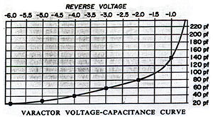
Notice the nonlinear increase in capacitance as the reverse voltage is decreased. This nonlinearity allows the varactor to be used also as a harmonic generator.
Major varactor considerations are:
(a) Capacitance value
(b) Voltage
(c) Variation in capacitance with voltage.
(d) Maximum working voltage
(e) Leakage current
Leave A Comment