TUNNEL DIODE
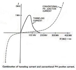
A tunnel diode is a semiconductor with a negative resistance region that results in very fast switching speeds, up to 5 GHz. The operation depends upon a quantum mechanic principle known as “tunneling” wherein the intrinsic voltage barrier (0.3 Volt for Germanium junctions) is reduced due to doping levels which enhance tunneling. Referring to the curves below, superimposing the tunneling characteristic upon a conventional P-N junction, we have:

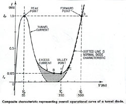
Resulting in a composite characteristic which is the tunnel diode characteristic curve.

The negative resistance region (between points A and B) is the important characteristic for the tunnel diode. In this region, as the voltage is increased, the current decreases; just the opposite of a conventional diode. The most important specifications for the tunnel diode are the Peak Voltage (Vp), Peak Current (Ip), Valley Voltage (Vv), and Valley Current (Iv).
BACK DIODE
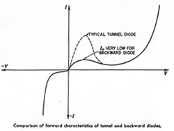
A Back diode is a tunnel diode with a suppressed Ip and so approximates a conventional diode characteristic. See the comparison below:

The reverse breakdown for tunnel diodes is very low, typically 200mV, and the TD conducts very heavily at the reverse breakdown voltage. Referring to the BD curve the back diode conducts to a lesser degree in a forward direction. It is the operation between these two points that makes the back diode important. Forward conduction begins at 300 mV (for germanium) and a voltage swing of only 500mV is required for full range operation.
Typical tunnel diodes supplied by American Microsemiconductor
|
Part Number
|
Ip Peak Point Current (mA) |
IV Valley Point Current Max. (mA) |
C Capacitance Max. (pF) |
VP Peak Point Voltage Typ. (mV) |
VV Valley Voltage Typ. (mV) |
Vfp Forward Peak Voltage Typ. (mV) |
RS Series Resist. Max. (ohms) |
-G Negative Conductance (mhosx10-3) |
fRO Resistive Cutoff Frequency Typ. (GHz) |
| 1N3712 | 1.0 + 10% |
0.18 |
10 |
65 |
350 |
500 |
4.0 |
8 Typ. |
2.3 |
| 1N3713 | 1.0 + 2.5% |
0.14 |
5 |
65 |
350 |
510 |
4.0 |
8.5 + 1 |
3.2 |
| 1N3714 | 2.2 + 10% |
0.48 |
25 |
65 |
350 |
500 |
3.0 |
18 Typ. |
2.2 |
| 1N3715 | 2.2 + 2.5% |
0.31 |
10 |
65 |
350 |
510 |
3.0 |
19 + 3 |
3.0 |
| 1N3716 | 4.7 + 10% |
1.04 |
50 |
65 |
350 |
500 |
2.0 |
40 Typ. |
1.8 |
| 1N3717 | 4.7 + 2.5% |
0.60 |
25 |
65 |
350 |
510 |
2.0 |
41 + 5 |
3.4 |
| 1N3718 | 10.0 + 10% |
2.20 |
90 |
65 |
350 |
500 |
1.5 |
80 Typ. |
1.6 |
| 1N3719 | 10.0 + 2.5% |
1.40 |
50 |
65 |
350 |
510 |
1.5 |
85 + 10 |
2.8 |
| 1N3720 | 22.0 + 10% |
4.80 |
150 |
65 |
350 |
500 |
1.0 |
180 Typ. |
1.6 |
| 1N3721 | 22.0 + 2.5% |
3.10 |
100 |
65 |
350 |
510 |
1.0 |
190 + 30 |
2.6 |
TYPICAL ULTRA HIGH-SPEED SWITCHING TUNNEL DIODES
SUPPLIED BY AMERICAN MICROSEMICONDUCTOR
|
Part Number
|
IP Peak point current (mA) |
IV Valley Point Current Max. (mA) |
C Capacitance Max. (pF) |
VP Peak Point Voltage Typical (mV) |
VV Valley Voltage Typical (mV) |
Vfp Forward Voltage Typical (mV) |
RS Series Resist. Typical (ohms) |
T Rise Time Typical (psec.) |
| TD-261 |
2.2 + 10% |
0.31 |
3.0 |
70 |
390 |
500-700 |
5.0 |
430 |
| TD-261A |
2.2 + 10% |
0.31 |
1.0 |
80 |
390 |
500-700 |
7.0 |
160 |
| TD-262 |
4.7 + 10% |
0.60 |
6.0 |
80 |
390 |
500-700 |
3.5 |
320 |
| TD-262A |
4.7 + 10% |
0.60 |
1.0 |
90 |
400 |
500-700 |
1.7 |
350 |
| TD-263 |
10.0 + 10% |
1.40 |
9.0 |
75 |
400 |
500-700 |
1.7 |
350 |
| TD-263A |
10.0 + 10% |
1.40 |
5.0 |
80 |
410 |
520-700 |
2.0 |
190 |
| TD-263B |
10.0 + 10% |
1.40 |
2.0 |
90 |
420 |
550-700 |
2.5 |
68 |
| TD-264 |
22.0 + 10% |
3.80 |
18.0 |
90 |
425 |
600 Typ. |
1.8 |
185 |
| TD-264A |
22.0 + 10% |
3.80 |
4.0 |
100 |
425 |
550-700 |
2.0 |
64 |
| TD-265 |
50.0 + 10% |
8.50 |
25.0 |
110 |
425 |
625 Typ. |
1.4 |
100 |
| TD-265A |
50.0 + 10% |
8.50 |
5.0 |
130 |
425 |
640 Typ. |
1.5 |
35 |
| TD-266 |
100 + 10% |
17.50 |
35.0 |
150 |
450 |
650 Typ. |
1.1 |
57 |
| TD-266A | 100 + 10% | 17.50 |
6.0 |
180 |
450 |
650 Typ. |
1.2 |
22 |


Leave A Comment